Installation & Debugging
Chapter 11 — Physical Installation Requirements, Initial Configuration, and Security Debugging
Successful router security deployment begins long before the first configuration command is entered. The physical installation environment, power infrastructure, grounding, and cable management all directly affect the security and reliability of the deployed system. This chapter covers the complete installation workflow from pre-installation site survey through physical mounting, initial secure configuration, and the debugging procedures for the most common security configuration issues.
11.1 Pre-Installation Site Survey
A thorough site survey must be completed before any hardware is ordered or shipped to the installation site. The site survey verifies that the physical environment meets all requirements for a secure, reliable router deployment. Issues identified during the site survey must be resolved before installation begins — attempting to work around environmental deficiencies during installation leads to compromises in both security and reliability.
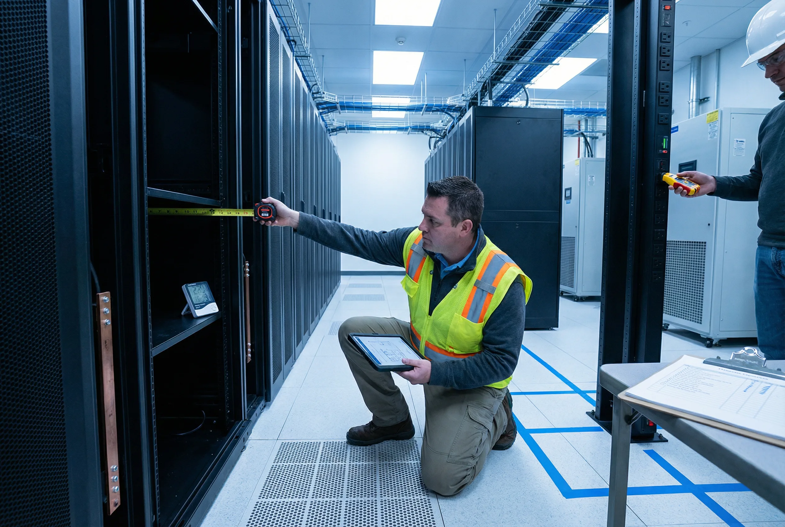
| Survey Item | Requirement | Measurement Method | Pass Criteria |
|---|---|---|---|
| Rack Space | Sufficient U-space for router + cable management + PDU + UPS | Count available U-spaces; measure rack depth | Minimum 10U free; rack depth ≥ 800mm for chassis routers |
| Power Circuits | Two independent power circuits (A and B) from separate breakers | Verify circuit breaker labels; test with circuit tester | Two circuits confirmed independent; correct voltage and amperage |
| Grounding | Rack ground bus bar connected to building ground; ground continuity verified | Continuity tester from rack ground bus to building ground | Resistance < 1 ohm; no breaks in ground path |
| Temperature | Ambient temperature 18–27°C (64–80°F); no hot spots above 35°C | Temperature sensor placed at front of rack at 1/3, 2/3, and top positions | All measurements within 18–27°C range |
| Humidity | Relative humidity 40–60%; no condensation | Humidity sensor placed in rack area | Humidity 40–60%; no visible condensation |
| Physical Access Control | Rack room has locked door with access control; camera coverage of rack area | Visual inspection; test access control system | Locked door with audit log; camera coverage confirmed |
| OOB Network Path | Dedicated OOB management network path to router location | Trace cable path from OOB switch to rack location | Dedicated Cat6A or fiber path confirmed; no shared production cables |
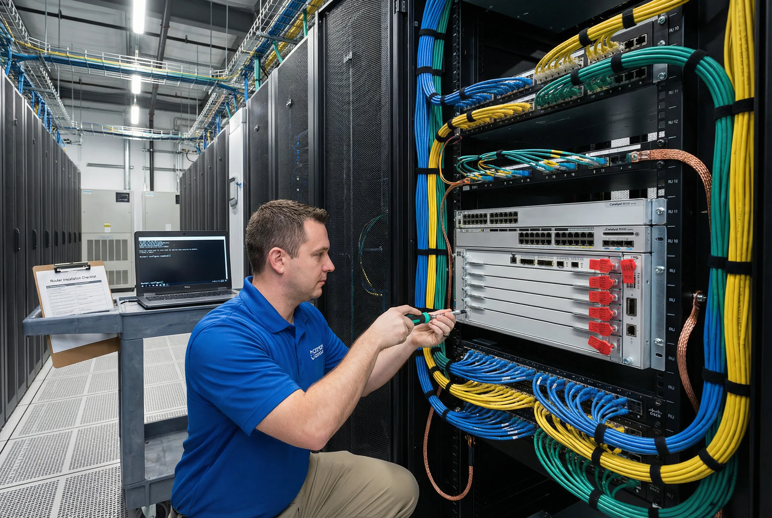
11.2 Physical Installation Requirements
Physical installation must follow a defined sequence to ensure that security controls are established before the router is connected to any network. The sequence below is mandatory: physical mounting and grounding must be completed and verified before power is applied, and initial secure configuration must be completed via console before any network interface is enabled.
| Step | Action | Security Requirement | Verification |
|---|---|---|---|
| 1 | Unbox and inspect | Verify serial number matches purchase order; check tamper-evident seals on shipping box; photograph any damage | Serial number confirmed; no tamper evidence; photos archived |
| 2 | Mount in rack | Use torque screwdriver at specified torque; do not over-tighten; install in designated rack unit position per rack diagram | Router securely mounted; rack diagram updated |
| 3 | Connect grounding cable | Connect router chassis ground lug to rack ground bus bar using 6 AWG green/yellow cable; verify continuity | Ground continuity < 1 ohm confirmed |
| 4 | Connect console cable | Connect yellow console rollover cable from router console port to terminal server; label both ends | Console session accessible via terminal server |
| 5 | Apply initial secure config via console | Apply complete security configuration via console BEFORE connecting any network cables; verify all security controls active | All acceptance test Phase 1 items pass via console verification |
| 6 | Connect OOB management cable | Connect blue Cat6A cable from OOB management port to OOB switch; verify management VRF routing | SSH accessible via OOB network; AAA authentication working |
| 7 | Connect power (both PSUs) | Connect PSU-A to PDU-A (Circuit-A); connect PSU-B to PDU-B (Circuit-B); verify redundant power | Both PSUs active; power supply redundancy confirmed |
| 8 | Connect production network cables | Connect production interfaces only after all security configuration is verified; label all cables at both ends | All cables labeled; production interfaces operational; routing sessions established |
| 9 | Apply tamper-evident seals | Apply serialized tamper-evident seals to unused ports, console port (if terminal server connected), and rack screws; record serial numbers | All seal serial numbers recorded in CMDB |
11.3 Common Security Configuration Issues & Debugging
The table below documents the most frequently encountered security configuration issues during router deployment, along with their symptoms, root causes, and resolution procedures. Engineers should consult this table before escalating issues, as the majority of deployment problems fall into these known categories.
| Issue | Symptom | Root Cause | Debug Command | Resolution |
|---|---|---|---|---|
| AAA Authentication Failure | SSH login fails with "Authentication failed"; local fallback not working | TACACS+ server unreachable; incorrect server key; wrong VRF for AAA traffic | debug aaa authentication; test aaa group TACACS+ |
Verify TACACS+ server reachability via OOB VRF; verify shared secret; check source interface binding |
| BGP Session Not Establishing | BGP neighbor stuck in Active or Connect state | Authentication mismatch; ACL blocking TCP 179; wrong source IP; TTL mismatch for EBGP multihop | debug ip bgp <peer> events; show bgp neighbors <peer> |
Verify MD5/TCP-AO key matches on both ends; check ACL permits TCP 179; verify update-source interface |
| CoPP Dropping Legitimate Traffic | BGP sessions flapping; OSPF adjacency drops; SNMP timeouts | CoPP rate limits too aggressive; legitimate traffic misclassified; burst size too small | show policy-map control-plane; show policy-map control-plane input class <name> |
Review CoPP statistics; increase rate limits for affected class; verify traffic classification ACLs |
| uRPF Dropping Valid Traffic | Asymmetric traffic paths failing; specific source prefixes unreachable | Asymmetric routing; uRPF strict mode on asymmetric path; missing return routes | show ip cef <source-ip>; debug ip packet <acl> detail |
Switch to uRPF loose mode on asymmetric interfaces; add allow-default option; verify routing table completeness |
| NTP Not Synchronizing | show ntp status shows "unsynchronized"; log timestamps incorrect | NTP server unreachable; authentication key mismatch; NTP ACL blocking | debug ntp events; show ntp associations detail |
Verify NTP server reachability via OOB VRF; verify authentication key matches; check NTP ACL |
| Syslog Not Received at Remote Server | No log messages appearing at syslog server; local buffer filling | Wrong syslog server IP; UDP 514 blocked by ACL; wrong VRF for syslog traffic; source interface not set | show logging; debug ip packet <acl> |
Verify syslog server IP; check ACL permits UDP 514; set logging source-interface to OOB interface; verify VRF |
11.4 Initial Secure Configuration Template
The following configuration template provides the minimum set of security commands that must be applied to every router before it is connected to any network. This template covers the most critical security controls and should be applied via console connection before any network interface is enabled. Platform-specific commands may vary; consult the vendor documentation for exact syntax.
! ============================================================
! INITIAL SECURE CONFIGURATION TEMPLATE
! Apply via console BEFORE connecting any network interfaces
! ============================================================
!
! 1. HOSTNAME AND DOMAIN
hostname <DEVICE-HOSTNAME>
ip domain-name <COMPANY.COM>
!
! 2. SSH KEY GENERATION (4096-bit RSA)
crypto key generate rsa modulus 4096
ip ssh version 2
ip ssh time-out 60
ip ssh authentication-retries 3
ip ssh source-interface GigabitEthernet0
!
! 3. DISABLE INSECURE SERVICES
no ip http server
no ip http secure-server
no cdp run
no lldp run
no service finger
no service tcp-small-servers
no service udp-small-servers
no ip bootp server
no ip source-route
!
! 4. MANAGEMENT VRF
vrf definition MGMT
 rd 65000:999
 address-family ipv4
  exit-address-family
!
! 5. AAA CONFIGURATION
aaa new-model
aaa authentication login default group TACACS+ local
aaa authentication enable default group TACACS+ enable
aaa authorization exec default group TACACS+ local
aaa authorization commands 15 default group TACACS+ local
aaa accounting exec default start-stop group TACACS+
aaa accounting commands 15 default start-stop group TACACS+
!
! 6. VTY LINES - SSH ONLY
line vty 0 15
 transport input ssh
 login authentication default
 exec-timeout 5 0
 logging synchronous
!
! 7. CONSOLE LINE
line con 0
 exec-timeout 5 0
 login authentication default
 logging synchronous
!
! 8. LOGIN BANNER
banner login ^
  *** AUTHORIZED USE ONLY ***
  This system is the property of [ORGANIZATION].
  Unauthorized access is prohibited and will be prosecuted.
  All activities are monitored and logged.
^
!
! 9. LOGGING
service timestamps log datetime msec localtime show-timezone
logging buffered 1048576 informational
logging trap informational
logging source-interface GigabitEthernet0 vrf MGMT
logging host <SYSLOG-SERVER-IP> vrf MGMT
!
! 10. NTP WITH AUTHENTICATION
ntp authenticate
ntp authentication-key 1 md5 <NTP-KEY>
ntp trusted-key 1
ntp source GigabitEthernet0
ntp server <NTP-SERVER-IP> key 1 prefer vrf MGMT
!
! END OF INITIAL SECURE CONFIGURATION TEMPLATE
! ============================================================