Scenarios & Selection
Chapter 3 — Eight Real-World Deployment Scenarios with Technical Specifications
Router security configuration requirements vary significantly across deployment contexts. This chapter presents eight distinct real-world deployment scenarios, each with a photorealistic site image, scenario description, primary security challenges, and key technical indicators. The goal is to help architects and engineers select the appropriate baseline profile and feature set for their specific environment.
3.1 Internet-Facing WAN Edge
Scenario 1: Dual-ISP WAN Edge with BGP and OOB Management
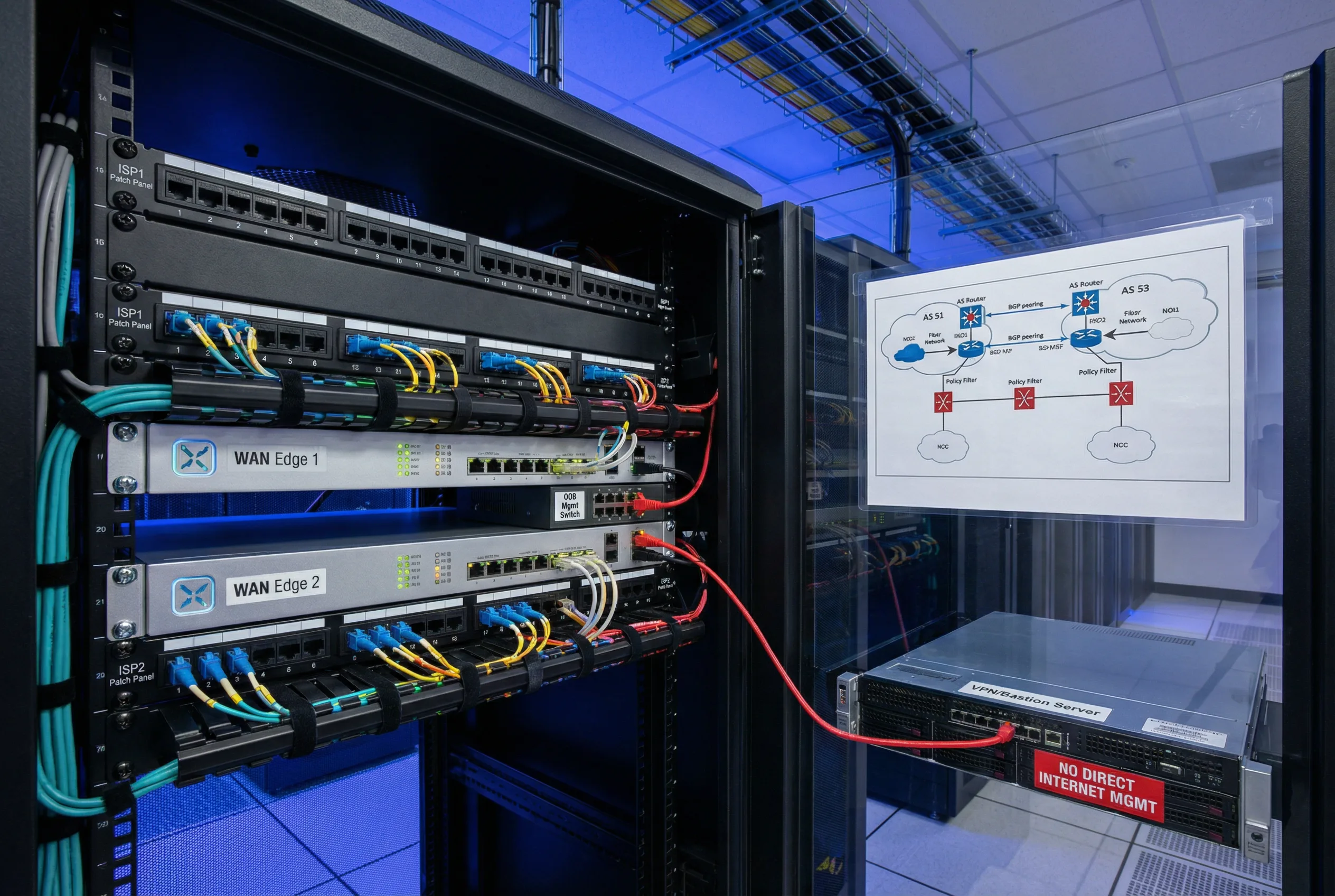
The WAN Edge scenario represents the highest-risk deployment context, where the router is directly adjacent to the public Internet and must handle untrusted BGP peering sessions from one or more ISPs. The primary security challenge is preventing unauthorized administrative access, route injection, and control-plane exhaustion while maintaining full BGP operational capability. A dedicated OOB management network physically separates administrative traffic from production traffic, and a VPN/bastion server enforces MFA before any CLI session is permitted.
This scenario requires Profile A (Strict) baseline: all management services restricted to the OOB VRF, BGP peer ACLs enforced on both ISP sessions, inbound route policies with explicit prefix-list and AS-path filters, RPKI origin validation, max-prefix limits with warning thresholds, CoPP with aggressive rate limits for BGP SYN and ICMP, and uRPF loose mode on all Internet-facing interfaces. Configuration changes require a commit-confirm timer and peer review.
3.2 Data Center Edge Router
Scenario 2: DC Edge with Redundant Power and Dual-Plane Management
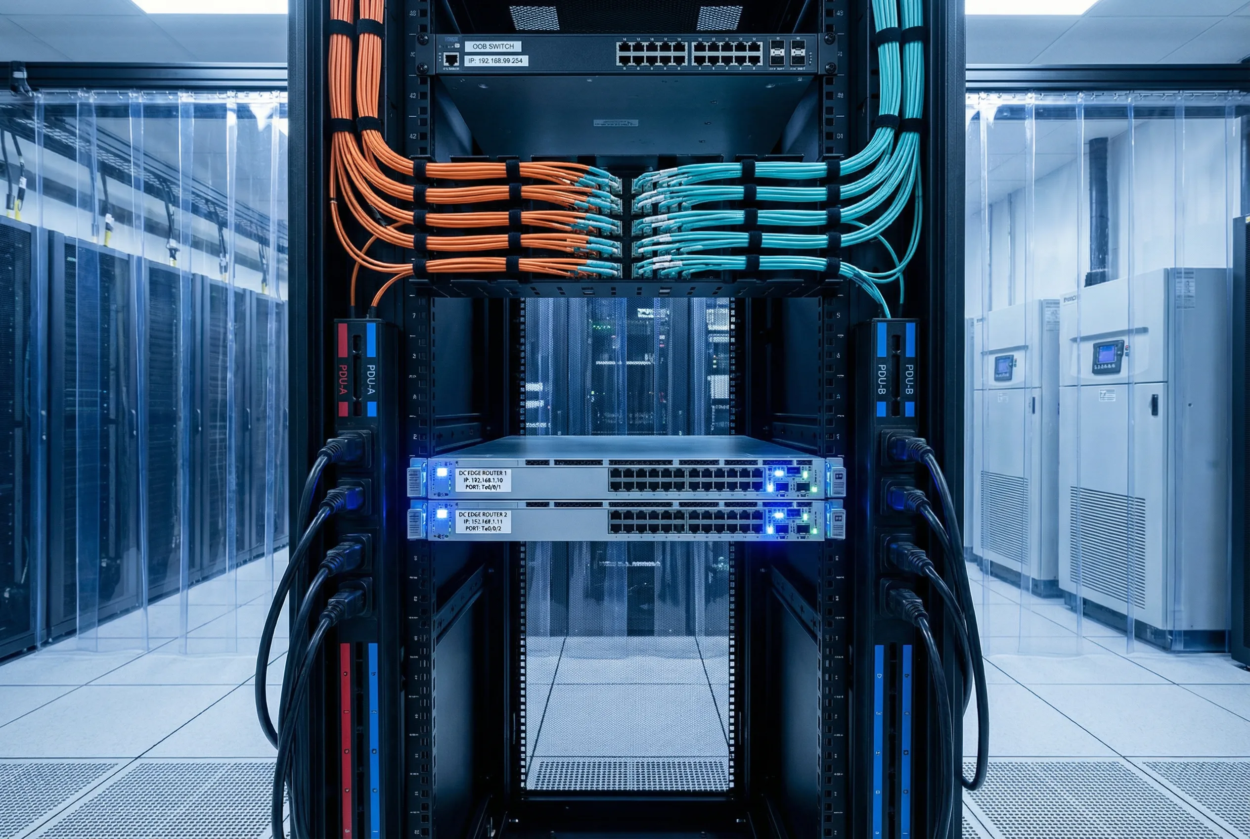
The DC Edge router sits at the boundary between the data center fabric and the WAN/Internet, handling both external BGP peering and internal iBGP sessions with route reflectors. The primary security requirements are strict VRF segmentation between tenant and management traffic, high availability with no single point of failure, and rigorous change control to prevent accidental route leaks between tenants or between the data center and external networks.
Dual power supplies connected to independent PDU-A and PDU-B rails ensure no power-related downtime. The OOB management switch at the top of the rack provides independent administrative access even when production interfaces are down. All configuration changes are applied via a configuration management platform with automated compliance checks and rollback capability.
3.3 Campus Core / Aggregation
Scenario 3: Multi-Building Campus Core with Fiber Ring and Admin VLAN
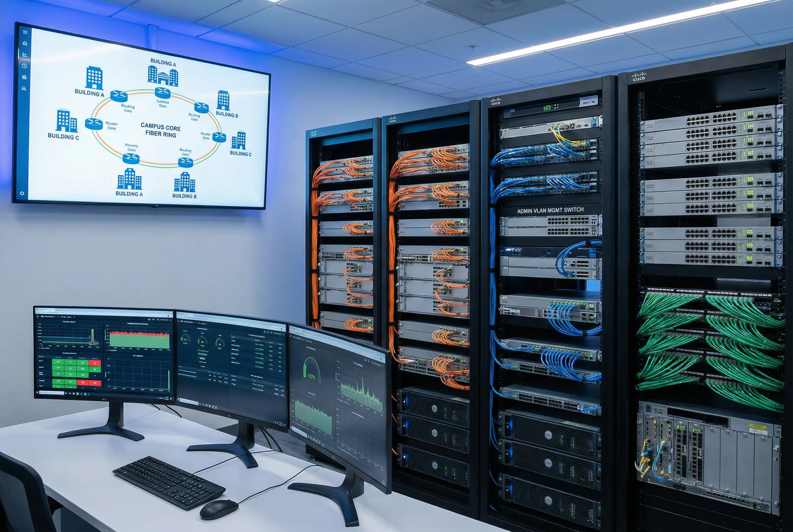
Campus core routers serve as the convergence point for multiple buildings, connecting to the WAN edge and providing routing services for user VLANs, server VLANs, and IoT/OT segments. The security challenge is managing a large number of OSPF/IS-IS neighbors across many interfaces while preventing unauthorized route injection from access layer switches and maintaining separation between user, server, and management traffic.
A dedicated admin VLAN (typically VLAN 99 or similar) carries all management traffic, isolated from user data. OSPF passive-interface is configured on all access-facing interfaces; only uplinks to distribution and WAN edge participate in OSPF. SNMPv3 monitoring feeds into the NOC dashboard showing real-time routing protocol status and CPU utilization across all campus routers.
3.4 Branch Gateway / SD-WAN CPE
Scenario 4: Branch Router with Dual WAN and ZTP Provisioning
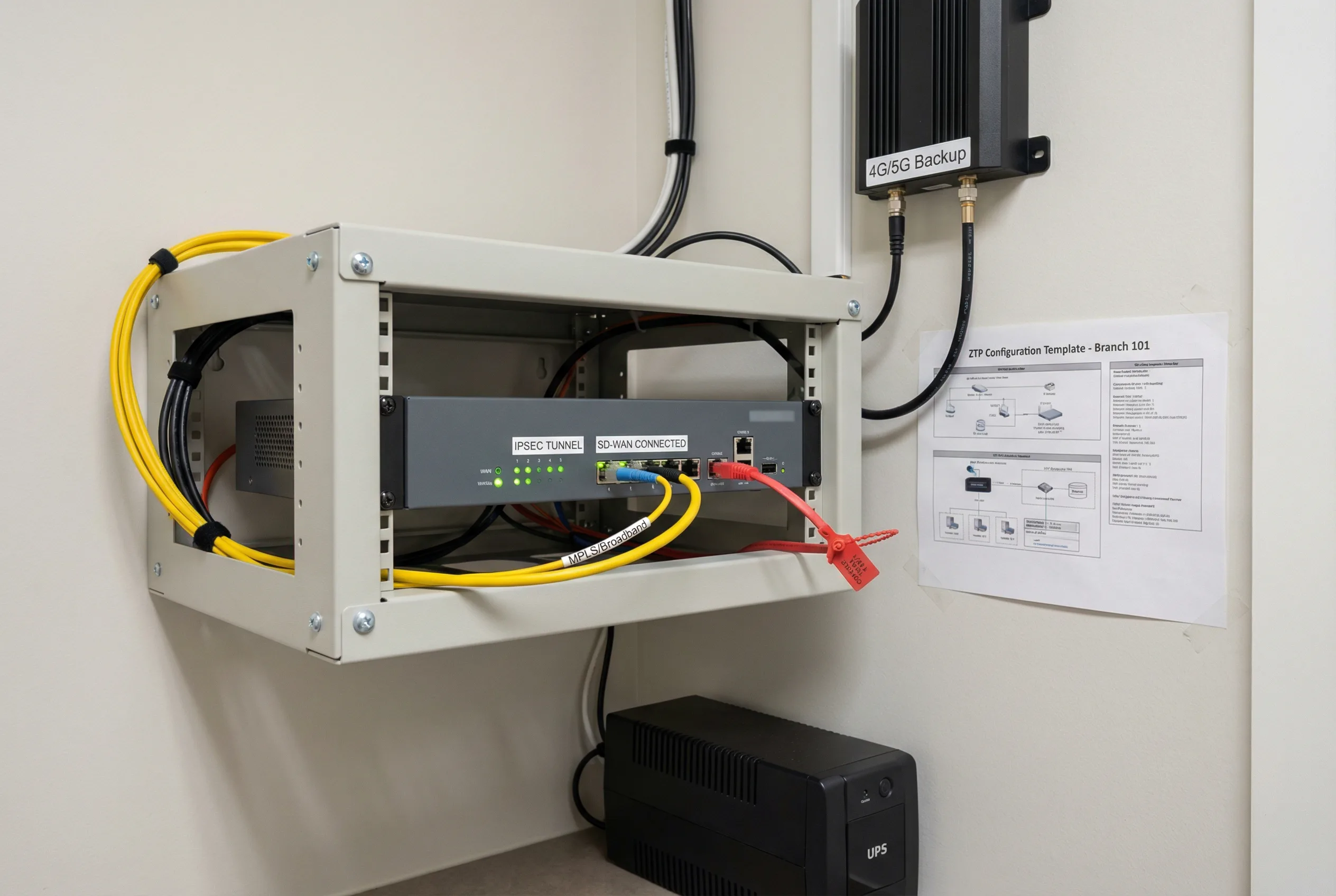
Branch routers present unique security challenges due to their distributed, often unstaffed locations and the need for zero-touch provisioning (ZTP) to enable rapid deployment without on-site expertise. Physical security is critical: the router must be mounted in a locked enclosure with tamper-evident seals, and the console port must be protected. Dual WAN connections — primary MPLS/broadband and backup 4G/5G cellular — provide resilience, with automatic failover and IPsec tunnel re-establishment.
ZTP templates pre-configure all security controls before the device is shipped, ensuring that the branch router is fully hardened from first boot. IPsec tunnels to the hub site carry all traffic, including management, preventing any direct Internet exposure of the router's management plane. A local UPS ensures the router remains operational during brief power outages.
3.5 OT / Industrial Network Perimeter
Scenario 5: IT/OT Boundary Router with Zone Separation and Physical Hardening
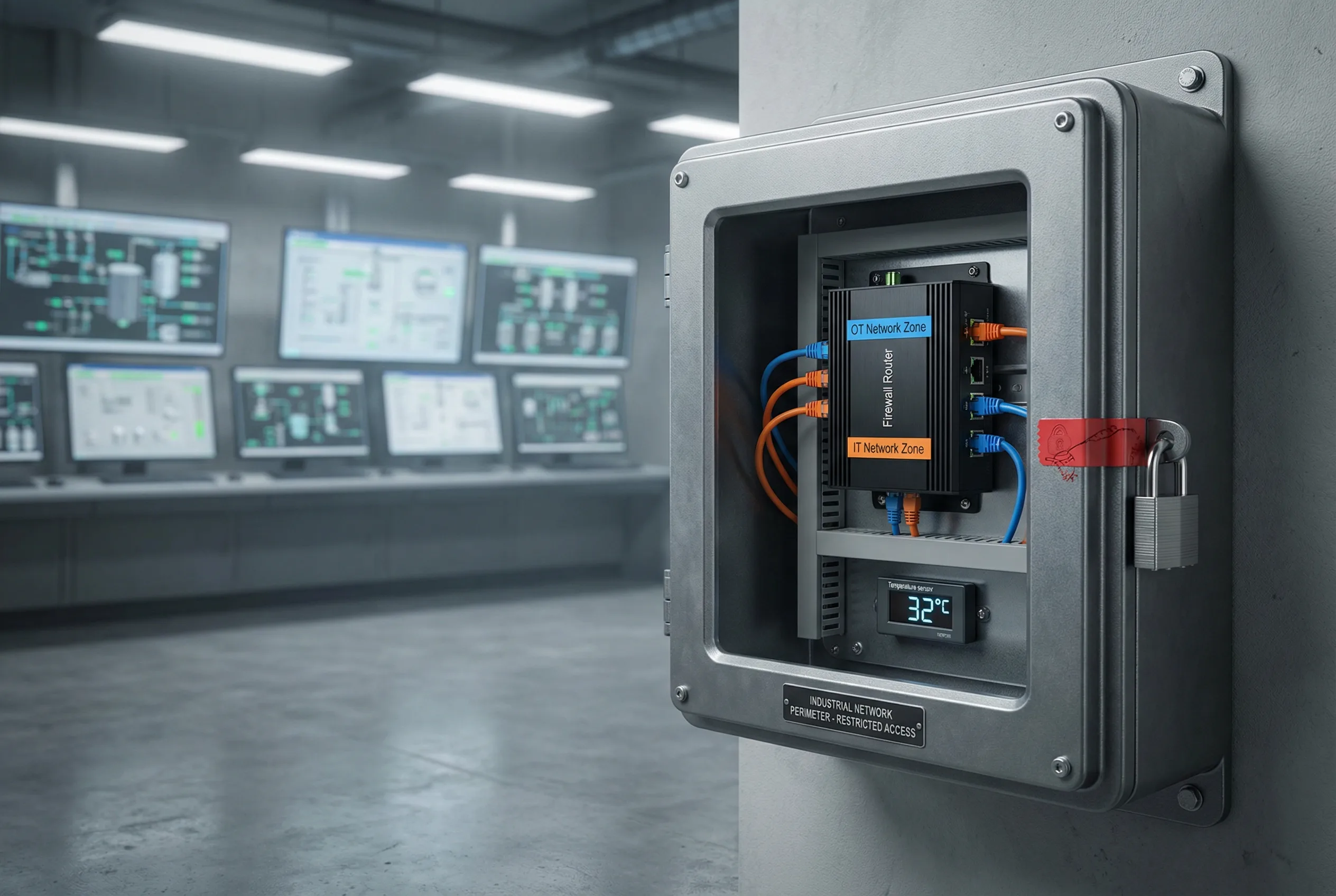
Industrial and OT network perimeters require the strictest possible access controls, as a compromise of the OT network can have physical safety consequences. The router at the IT/OT boundary must enforce strict zone separation: only explicitly permitted traffic flows between the IT and OT zones, with default deny in both directions. The device must be ruggedized for industrial environments (extended temperature range, vibration tolerance, DIN-rail mounting) and physically secured with a locked enclosure and tamper-evident seals.
Change management for OT boundary routers requires additional approval steps and a longer change freeze window aligned with industrial maintenance schedules. Remote access is strictly limited to specific maintenance windows with dual-person authorization. All access attempts are logged and alerted to both IT security and OT operations teams.
3.6 Partner Extranet / B2B Interconnect
Scenario 6: Partner Extranet Router with Per-Partner VLAN and BGP Route Filtering
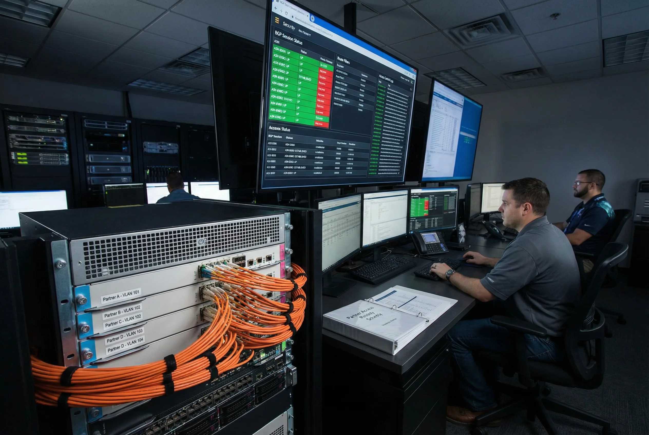
Partner extranet routers connect the enterprise network to multiple external business partners, each requiring strictly controlled access to specific internal resources. Each partner is isolated in a dedicated VLAN and VRF, preventing any cross-partner traffic leakage. BGP sessions with partner ASNs are tightly controlled: only specific prefixes are accepted from each partner, and only specific prefixes are advertised to each partner, enforced by per-partner prefix-lists.
A monthly access review process validates that all partner BGP sessions and route advertisements remain aligned with current business agreements. Any partner whose contract has expired or changed scope must have their BGP session and VLAN reconfigured before the next review cycle. The NOC dashboard provides real-time visibility into all partner BGP session states and route filter policy compliance.
3.7 Cloud On-Ramp / Hybrid Cloud
Scenario 7: Cloud Direct Connect with BGP Route Reflector and VRF Separation
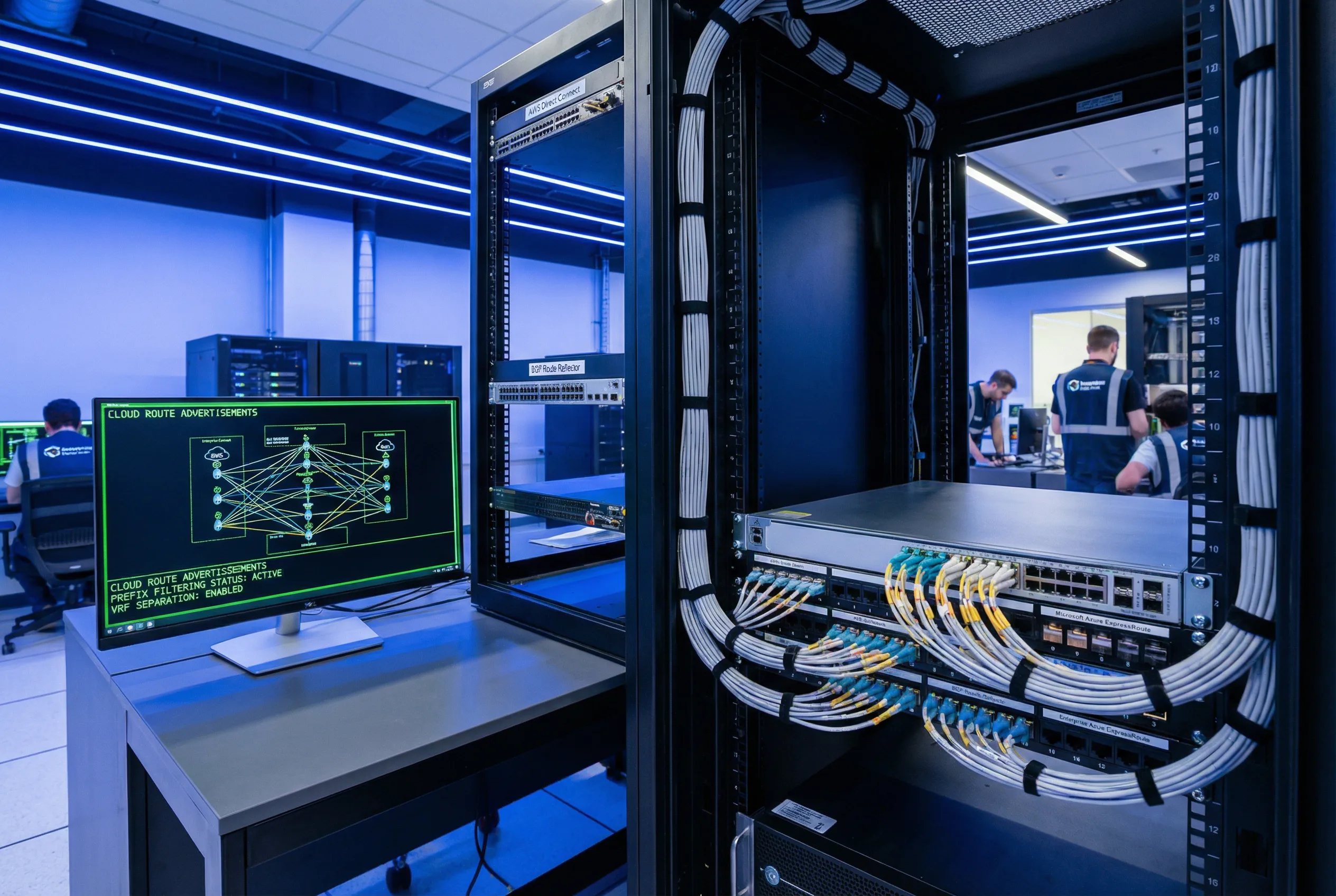
Cloud on-ramp routers provide dedicated private connectivity to cloud providers (AWS Direct Connect, Azure ExpressRoute, Google Cloud Interconnect) and must enforce strict separation between cloud route advertisements and on-premises routing domains. The primary risk is inadvertent route leakage between cloud environments or between cloud and Internet, which could expose internal resources or create routing loops.
A BGP route reflector in the adjacent rack consolidates iBGP sessions, reducing the number of full-mesh sessions required. VRF separation ensures that cloud-destined traffic and on-premises traffic are forwarded through independent routing tables. Prefix filtering is applied at both the cloud provider interface and the internal iBGP sessions, with automated monitoring to detect any unexpected route advertisements.
3.8 Service Provider Edge (PE Router)
Scenario 8: Carrier-Grade PE Router with MPLS, OOB Terminal Server, and Large-Scale NOC
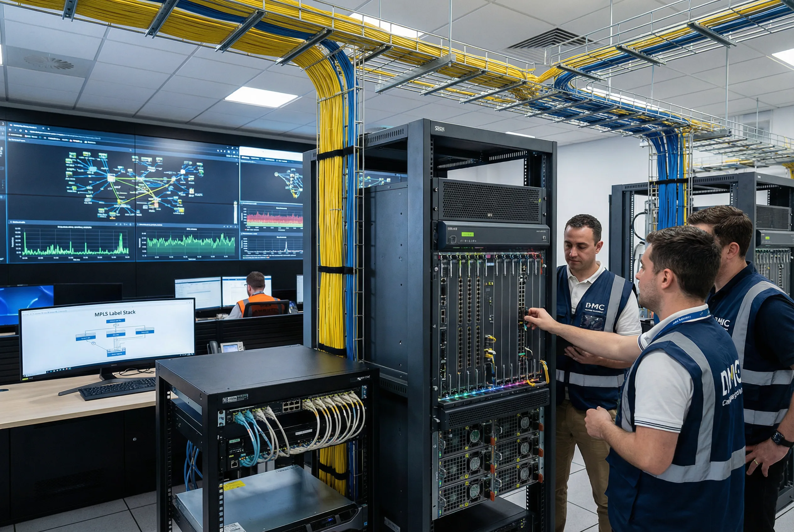
Service provider edge (PE) routers operate at the highest scale and complexity, handling thousands of BGP sessions, millions of routes, and hundreds of MPLS VPN customers simultaneously. The security requirements are correspondingly stringent: strict separation between customer VRFs, protection of the provider's own routing infrastructure from customer-originated attacks, and high availability with no single point of failure in hardware or software.
A dedicated OOB terminal server rack provides independent console access to all PE routers, ensuring that administrative access is always available even when production interfaces are down. The carrier NOC video wall provides real-time visibility into network topology, traffic levels, and security events across the entire service provider infrastructure. All configuration changes follow a formal change management process with multiple approval levels and automated pre/post-change verification.
3.9 Scenario Comparison & Baseline Profile Selection
The table below provides a consolidated comparison of all eight deployment scenarios across the key selection dimensions. Use this table to identify the appropriate baseline profile and feature set for your specific deployment context.
| Scenario | Baseline Profile | Mgmt Isolation | Routing Auth | Anti-Spoof | CoPP Level | Change Control |
|---|---|---|---|---|---|---|
| WAN Edge | Profile A (Strict) | OOB VRF + MFA | TCP-AO + RPKI | uRPF Loose | Aggressive | Commit-confirm + peer review |
| DC Edge | Profile A (Strict) | OOB VRF + MFA | MD5 / TCP-AO | uRPF Strict | Aggressive | Automated compliance + rollback |
| Campus Core | Profile B (Standard) | Admin VLAN | OSPF SHA-256 | ACL-based | Standard | Change ticket + staged commit |
| Branch / SD-WAN | Profile B (Standard) | IPsec to hub | IKEv2 PSK/Cert | ACL-based | Standard | ZTP template + auto-rollback |
| OT Perimeter | Profile A (Strict) | Maintenance window only | Static routes only | Default deny | Aggressive | Dual-person + change freeze |
| Partner Extranet | Profile A (Strict) | OOB VRF | TCP-AO per partner | Per-partner ACL | Aggressive | Monthly review + peer review |
| Cloud On-Ramp | Profile B (Standard) | Mgmt VRF | MD5 / TCP-AO | Prefix filter | Standard | Automated monitoring + rollback |
| SP Edge (PE) | Profile A (Strict) | OOB terminal server | TCP-AO + RPKI | uRPF + ACL | Carrier-grade | Multi-level approval |