Architecture Design
Chapter 4 — Typical System Topology, Device Wiring, and Configuration Specifications
4.1 Typical System Topology
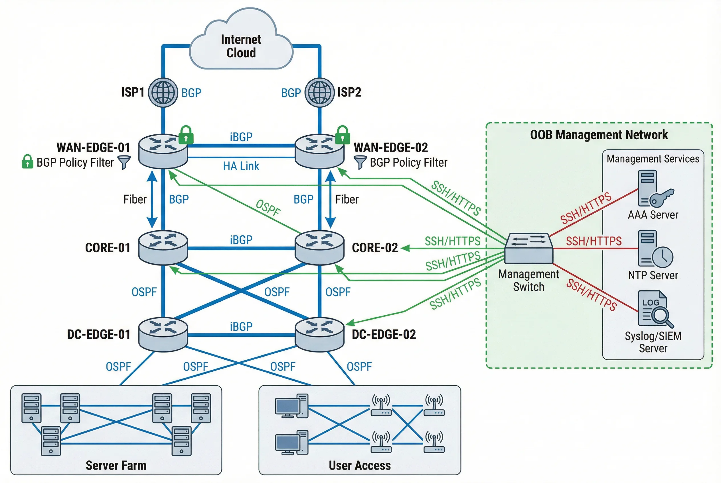
The typical enterprise router security architecture follows a hierarchical, multi-tier design that enforces strict plane separation at every layer. The topology diagram below illustrates the complete system, showing how WAN Edge, Core, and DC Edge routers are interconnected through production links (blue), while a completely separate OOB Management Network (green) provides independent administrative access to all devices. This separation ensures that even a complete production network failure does not prevent administrative access for recovery operations.
The architecture places BGP policy filters at every external peering point, OSPF authentication on all internal links, and iBGP sessions between routers in the same tier. The Management Services cluster — comprising AAA Server, NTP Server, and Syslog/SIEM Server — is reachable only through the OOB network, preventing any production traffic from reaching these critical infrastructure components.
Topology Design Rationale
The three-tier hierarchy (WAN Edge → Core → DC Edge) provides multiple points of security enforcement: WAN Edge applies external BGP policy and anti-spoof; Core applies internal routing policy and VRF segmentation; DC Edge applies tenant isolation and data-plane ACLs. This defense-in-depth approach ensures that a misconfiguration or compromise at one tier does not automatically expose all resources.
| Tier | Device Role | Routing Protocols | Security Controls | Redundancy |
|---|---|---|---|---|
| WAN Edge | External BGP peering, Internet boundary | eBGP (ISP), iBGP (core) | BGP policy filter, peer ACL, uRPF, CoPP, RPKI | Active/Active HA pair |
| Core | Internal routing, VRF distribution | OSPF/IS-IS, iBGP | OSPF auth, route policy, CoPP, VRF segmentation | Dual-home to both WAN Edge routers |
| DC Edge | Data center boundary, tenant isolation | OSPF/IS-IS, iBGP | Tenant VRF, data-plane ACL, uRPF strict, CoPP | Active/Active HA pair |
| OOB Mgmt | Out-of-band administrative access | Static routes only | Mgmt VRF, SSH only, AAA, MFA, session recording | Separate physical network |
4.2 Device Wiring & Connection Diagram
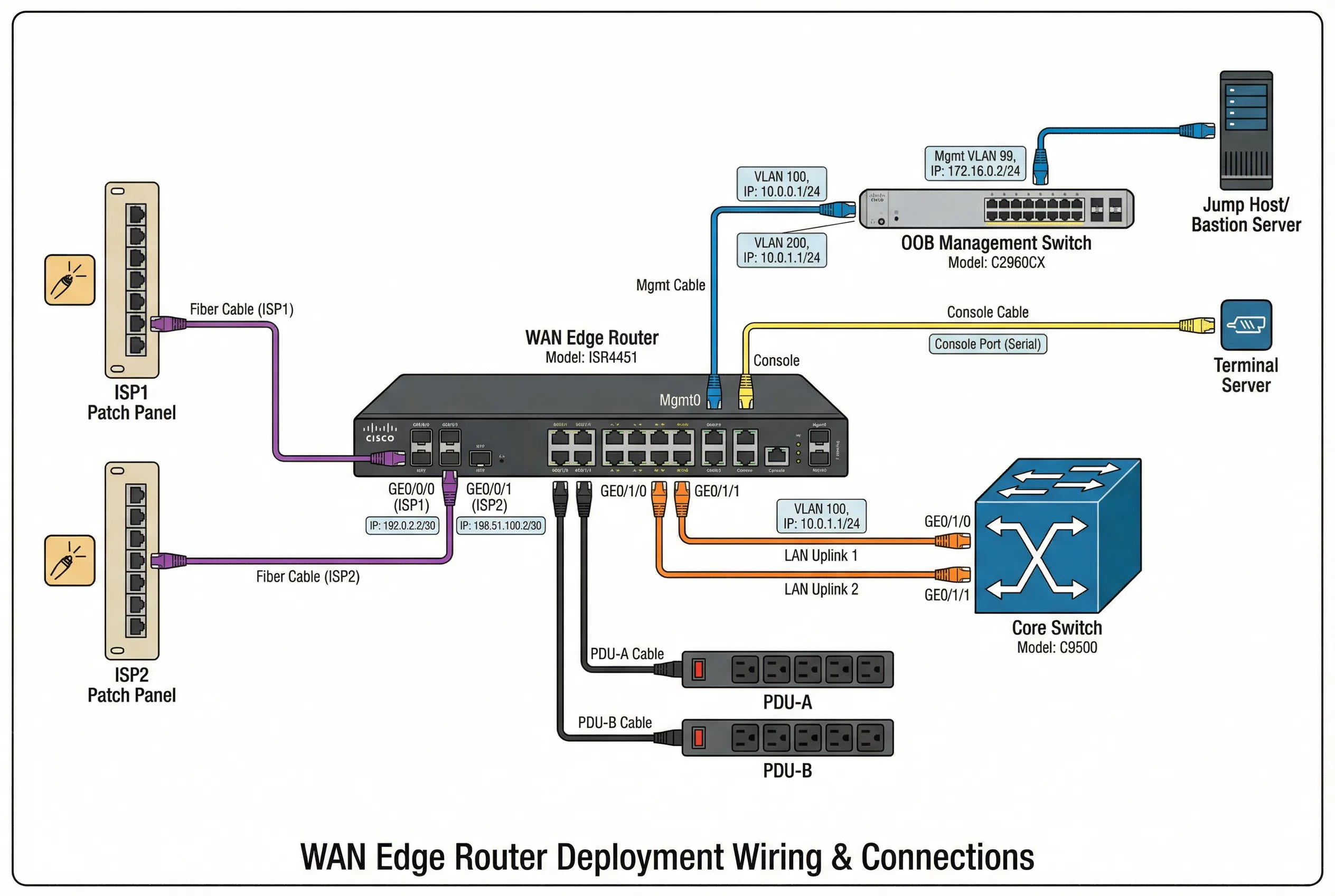
The device wiring diagram provides a detailed view of the physical and logical connections for a WAN Edge router deployment. Each interface is labeled with its logical role, IP address, VRF assignment, and cable type, enabling field engineers to verify the installation without referencing separate documentation. Color-coded cables distinguish production traffic (orange), management traffic (blue), and console access (yellow), reducing the risk of mis-cabling during installation or maintenance.
The diagram shows the complete connection set: ISP patch panels feeding the WAN interfaces, core switch uplinks carrying production traffic, OOB management switch providing independent administrative access, terminal server enabling console access for emergency recovery, and dual PDU connections ensuring power redundancy. Every connection is labeled with the interface name, IP address, and VLAN assignment.
Wiring Standards and Best Practices
- Cable color coding: Orange = production/transit, Blue = management/OOB, Yellow = console/serial, Red = power, Green = monitoring/SPAN.
- Label requirements: Every cable must be labeled at both ends with interface name, remote device, and port number. Labels must be machine-readable and human-readable.
- Console port protection: Console port must have a tamper-evident seal when not in use. Console access must be logged via the terminal server.
- Power separation: Router must be connected to two independent PDUs on separate power circuits. Never connect both power supplies to the same PDU.
- Fiber management: Fiber cables must be routed through cable management trays with bend radius protection. Minimum bend radius must not be violated.
- Documentation: As-built wiring diagram must be updated within 24 hours of any physical change and stored in the configuration management system.
4.3 Configuration Architecture
The configuration architecture defines how security controls are organized within the router's configuration, ensuring that all controls are consistently applied and easily auditable. The architecture follows a modular approach: each security domain (management plane, routing protocol, data plane) has its own configuration block with clear boundaries and dependencies. This modularity enables targeted changes without risk of unintended interactions between security domains.
| Configuration Domain | Key Configuration Elements | Template Reference | Verification Command |
|---|---|---|---|
| Management Plane | SSH v2 only, HTTPS with TLS1.2+, SNMPv3 authPriv, AAA config, login banners, session timeout, lockout policy | MGMT-PLANE-TEMPLATE-v2 | show ip ssh; show aaa servers; show line |
| AAA / RBAC | TACACS+ / RADIUS server groups, authentication lists, authorization lists, accounting lists, local break-glass account | AAA-RBAC-TEMPLATE-v2 | show aaa method-lists; test aaa |
| Routing Protocol Security | BGP peer ACL, MD5/TCP-AO keys, prefix-lists, route-maps, max-prefix, OSPF auth keys, passive-interface | ROUTING-SEC-TEMPLATE-v3 | show bgp neighbors; show ip ospf neighbor |
| Control-Plane Protection | CoPP policy-map with class-maps for BGP, OSPF, ICMP, SSH, SNMP, ARP, fragments; rate limits per class | COPP-TEMPLATE-v2 | show policy-map control-plane; show platform resources |
| Data-Plane ACL | Ingress ACL per interface, egress ACL, uRPF mode, anti-spoof prefix-list, VRF route-leaking policy | ACL-TEMPLATE-v3 | show ip access-lists; show ip verify source |
| Logging & Time | NTP server with auth, syslog targets with severity, logging buffer, timestamps with msec, archive logging | LOG-TIME-TEMPLATE-v2 | show ntp status; show logging; show clock detail |
| Config Backup | TFTP/SCP backup schedule, archive config, config change notification, rollback procedure, golden image reference | BACKUP-TEMPLATE-v2 | show archive; show running-config | checksum |
4.4 High Availability & Redundancy Design
High availability design for router security deployments must balance redundancy against configuration consistency. Both routers in an HA pair must have identical security configurations, including all ACLs, CoPP policies, routing protocol authentication keys, and AAA settings. Configuration drift between HA peers is a common source of security incidents and must be actively detected and remediated.
| HA Dimension | Design Choice | Security Implication | Monitoring Requirement |
|---|---|---|---|
| Router Redundancy | Active/Active HA pair with ECMP or HSRP/VRRP | Both routers must have identical security configs; config drift creates security gaps | Config diff check between peers; alert on any difference |
| BGP Session Redundancy | Each router maintains independent BGP sessions to all peers | Authentication keys must be synchronized; key rotation must be coordinated | BGP session state on both routers; alert on asymmetric state |
| Management Access Redundancy | OOB network with independent path to both routers | OOB network must also be secured; single OOB switch is a management SPOF | OOB reachability test from jump host; alert on loss |
| AAA Redundancy | Primary + secondary AAA servers; local break-glass as last resort | Break-glass account must be tightly controlled; every use must be alerted | AAA server availability; break-glass usage alert |
| Power Redundancy | Dual PSU on independent PDU circuits | No security implication if properly implemented | PSU status; PDU circuit load; alert on PSU failure |