A complete router security deployment requires a comprehensive set of accessories covering cables
and connectivity, physical security hardware, power components, and documentation materials.
This chapter provides a visual reference and detailed specification table for all required
accessories, enabling procurement teams to build accurate bills of materials and field engineers
to verify completeness before beginning installation.
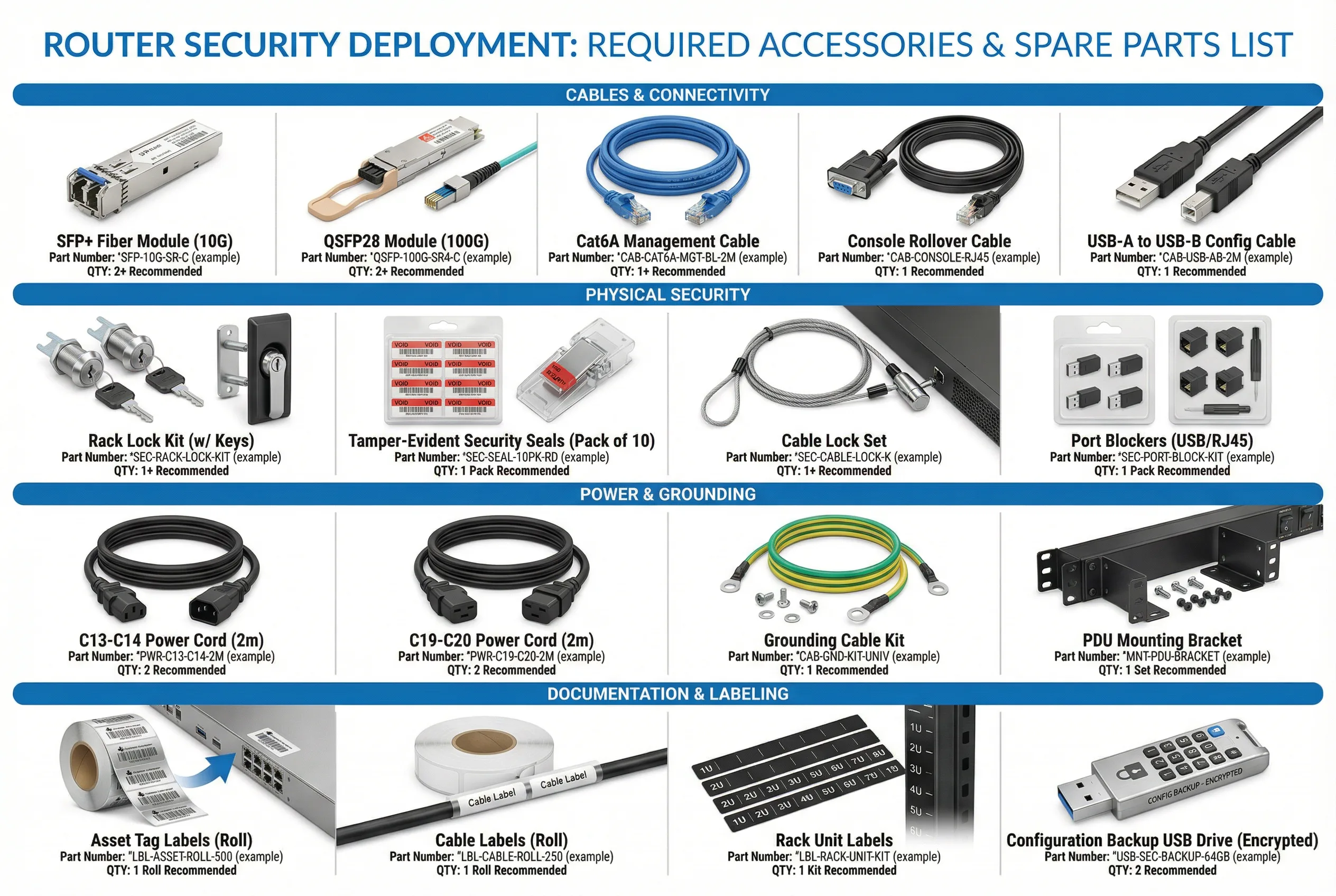
8.1 Accessories Visual Reference
The accessories reference image below shows all required items organized by category: Cables &
Connectivity, Physical Security, Power & Grounding, and Documentation & Labeling. Each item
is shown with its name, example part number format, and recommended quantity. Actual part numbers
will vary by vendor and router model — consult the router vendor's compatibility matrix for
specific part numbers.
8.2 Cables & Connectivity
| Item |
Specification |
Use Case |
Min. Qty per Router |
Notes |
| SFP+ Fiber Module (10G) |
10GBASE-SR (multimode) or 10GBASE-LR (single-mode); vendor-compatible |
WAN uplinks, core uplinks, monitoring SPAN |
2–4 (depending on port count) |
Use vendor-approved optics; third-party may not be supported |
| QSFP28 Module (100G) |
100GBASE-SR4 or 100GBASE-LR4; vendor-compatible |
High-capacity WAN or DC uplinks |
0–2 (if 100G ports used) |
Required only for Edge and SP chassis routers |
| Cat6A Management Cable |
Cat6A shielded; 2m length; blue color for management identification |
OOB management port to OOB switch |
1 |
Blue color coding for management traffic identification |
| Console Rollover Cable |
RJ45-to-DB9 or RJ45-to-USB; 1.8m length; yellow color |
Console port to terminal server |
1 |
Yellow color coding for console/serial identification |
| USB Config Cable |
USB-A to USB-B or USB-A to mini-USB; 1m length |
Configuration backup to encrypted USB drive |
1 |
Store in locked cabinet when not in use |
8.3 Physical Security Accessories
| Item |
Specification |
Use Case |
Min. Qty per Router |
Notes |
| Rack Lock Kit |
Rack door lock with 2 keys; keyed-alike option available for site-wide consistency |
Prevent unauthorized physical access to router rack |
1 per rack |
Keys must be managed in a key management system; loss must be reported |
| Tamper-Evident Seals |
Serialized security seals; void-on-removal; red color; pack of 10 |
Seal console port, unused interface ports, and rack screws |
1 pack (10 seals) |
Serial numbers must be recorded; broken seals trigger security incident |
| Cable Lock Set |
Steel cable lock; 1.5m cable; combination or keyed lock |
Secure router to rack in environments without locked rack doors |
1 (if no rack door lock) |
Secondary physical security measure |
| Port Blockers (USB/RJ45) |
Physical port blockers for USB and RJ45 ports; keyed removal; pack of 10 |
Block unused USB and RJ45 ports to prevent unauthorized device connection |
1 pack |
Required for all unused ports; document which ports are blocked |
8.4 Power & Grounding Accessories
| Item |
Specification |
Use Case |
Min. Qty per Router |
Notes |
| C13-C14 Power Cord (2m) |
IEC C13 to C14; 10A/250V; 2m length; red color for PDU-A, black for PDU-B |
Router PSU to PDU connection |
2 (one per PSU) |
Color coding: red = PDU-A, black = PDU-B |
| C19-C20 Power Cord (2m) |
IEC C19 to C20; 16A/250V; 2m length; for high-power chassis routers |
High-power router PSU to PDU connection |
2 (if C19 PSU) |
Required for chassis routers with >1500W PSU |
| Grounding Cable Kit |
Green/yellow grounding cable; ring terminals; 1.5m length; 6 AWG minimum |
Router chassis to rack ground bus connection |
1 |
Required for all deployments; verify ground continuity after installation |
| PDU Mounting Bracket |
0U vertical PDU mounting bracket; fits standard 19" rack; adjustable position |
Mount PDU vertically in rack to maximize U-space |
1 per PDU |
Vertical mounting preferred to preserve rack U-space |
8.5 Documentation & Labeling Materials
| Item |
Specification |
Use Case |
Min. Qty per Site |
Notes |
| Asset Tag Labels |
Serialized barcode/QR labels; tamper-evident; roll of 500; compatible with asset management system |
Asset identification and tracking for all hardware |
1 roll per site |
Asset tags must be registered in CMDB before device is placed in service |
| Cable Labels |
Wrap-around cable labels; laser-printable; roll of 250; various sizes for different cable diameters |
Label all cables at both ends with interface name and remote device |
1 roll per site |
Labels must be printed, not handwritten; use standard naming convention |
| Rack Unit Labels |
Adhesive rack unit labels (1U–10U); numbered; fits standard 19" rack rails |
Identify rack unit positions for documentation and troubleshooting |
1 kit per rack |
Rack diagrams must match physical rack unit labels |
| Config Backup USB Drive |
Encrypted USB drive; hardware encryption (AES-256); 64GB minimum; PIN-protected |
Local configuration backup and emergency recovery |
2 per router (primary + backup) |
Store in separate physical locations; test recovery procedure quarterly |
8.6 Recommended Spare Parts Inventory
Maintaining a spare parts inventory reduces mean time to repair (MTTR) for hardware failures.
The table below provides minimum spare parts recommendations based on deployment scale.
Critical spares (those whose failure causes immediate service impact) should be stocked on-site;
non-critical spares may be stored at a regional depot.
| Spare Part |
Priority |
1–5 Routers |
6–20 Routers |
20+ Routers |
Storage Location |
| Power Supply Unit (PSU) |
Critical |
1 spare |
2 spares |
5% of deployed count |
On-site |
| SFP+ Fiber Module (10G) |
Critical |
2 spares |
4 spares |
10% of deployed count |
On-site |
| Console Rollover Cable |
High |
1 spare |
2 spares |
5 spares |
On-site |
| Management Ethernet Cable |
High |
2 spares |
5 spares |
10 spares |
On-site |
| Tamper-Evident Seals |
High |
1 pack |
2 packs |
5 packs |
On-site (locked) |
| Encrypted USB Drive |
Medium |
1 spare |
2 spares |
5 spares |
On-site (locked) |
| Line Card / Interface Module |
Medium |
0 (depot) |
1 spare |
2% of deployed count |
Regional depot |